September 29th, 2011
Grabbed 100 expansion joint ties as specified by the engineers from Bianco for $118.80
United Fastners for some extra bolts as we are losing a few to thread damage from grit and so on $35.40
Total project spend is now at $292,687.11
House only is now $78,734.61
Cost per square metre is now $273.38
Posted in Project Costs | No Comments »
September 17th, 2011
It’s actually been some time since we spent any money on the build. We’ve finally depleted our white cement stores so I had to grab another pallet this week, and our OB insurance cover needed extending.
Bianco for 80 bags of white cement – $674.08
Allrisk Pty Ltd for OB insurance – $473
Total project spend is now at $292,532.91
House only is now $78,580.41
Cost per square metre is now $272.85
Posted in Project Costs | No Comments »
September 8th, 2011
Posted in Building Progress | No Comments »
September 1st, 2011
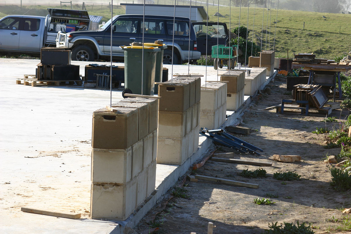
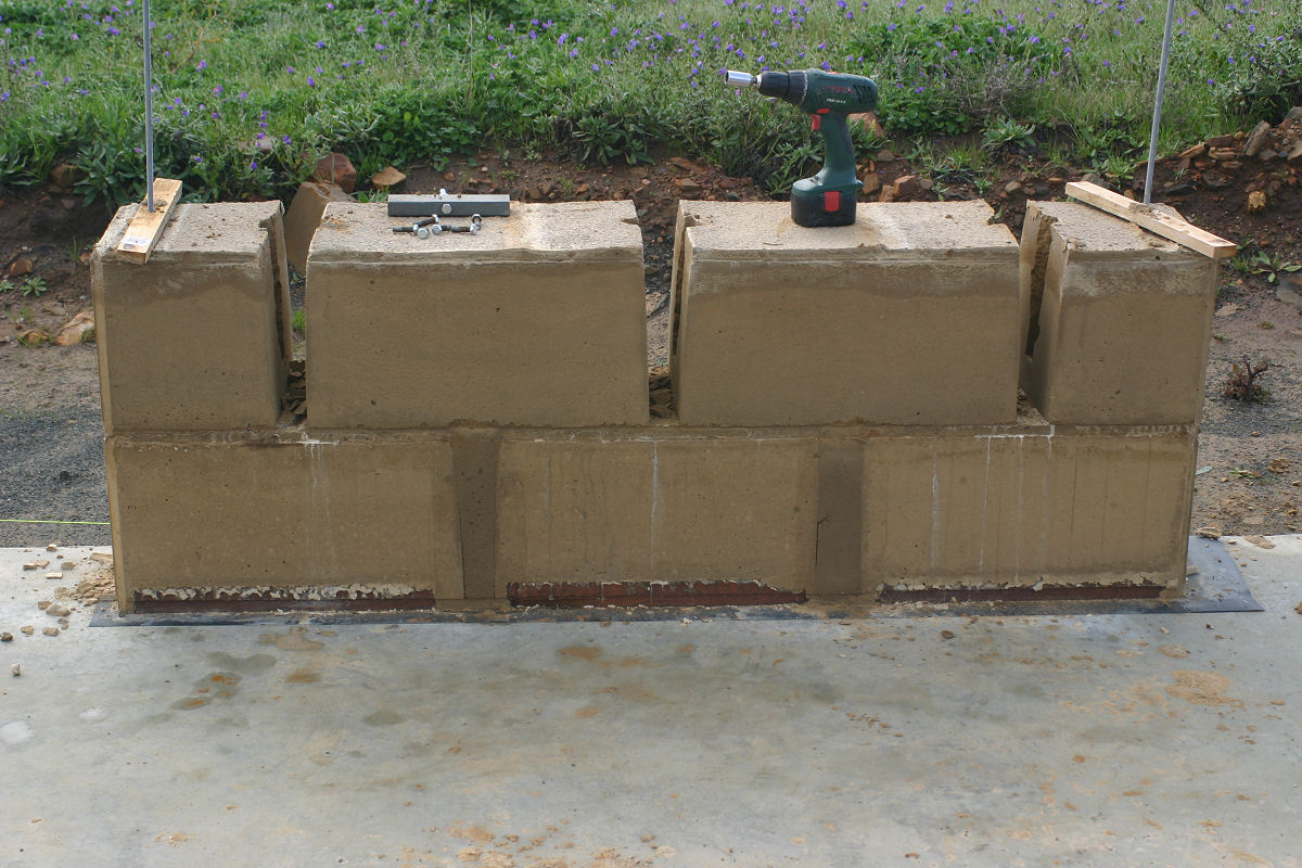
After nada for so long we can actually brag about making some progress with the house build. This first layer as I have said in previous posts is a drawn out process which is slowing things down for now. First pic below shows the “front” of the house from the master bedroom end. Currently the highest we have poured is three courses, the full height of these walls is nine courses.
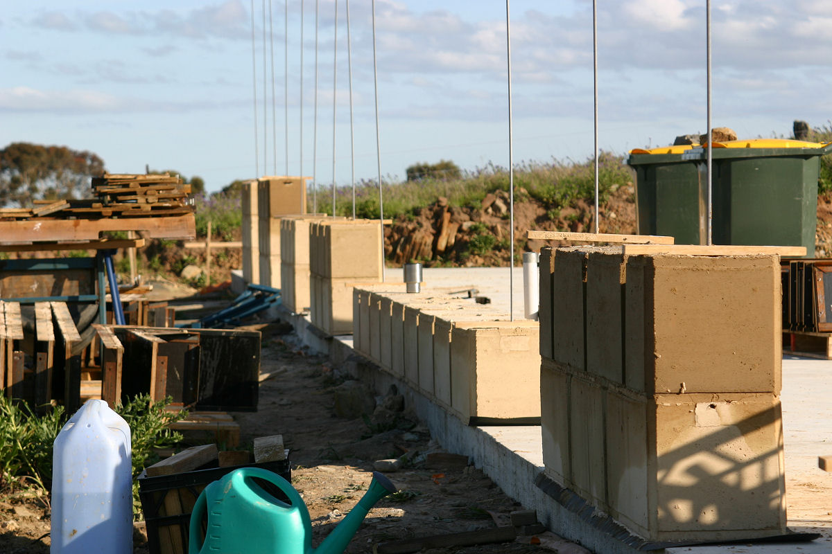
Second pic is the moulds set and ready to pour for the second course of the kitchen area of the house. I have been assisted by my father-in-law for much of the work so far and thanks again Roger, your help is truly appreciated. Third pic is meant to show just how much water I am pouring into the previous bricks to stop the void cracking problem we had encountered with the power room.


As a carry over from the third pic above, the first pic below demonstrates just how the moisture from the new layer is drawn into the previous blocks as seen in the middle group of blocks. Second pic below is old truck and new bus. The Pajero lives on as storage for now and is quite handy to stash things between trips back to town. Last pic shows the kitchen wall area before the moulds were reset. Again you can see just how much moisture the previous layer of blocks is capable of absorbing in the grouping closest to lens.


So far the results we are achieving are pleasing. I’m looking forward to completing the lower level of blocks around the perimeter of the house, from there the pace of the build will increase. We are seeing days in the mid 20’s already which is a bonus with the moulds now coming off after 24 hours. On the downside as things warm up and materials dry out I am already using 5 litres more water per batch compared to last week and having to mix the soil and water for longer to activate the clay. Put simply I now have to keep a very keen eye on the mixes to make sure they look right in texture and mositure to keep our end result consistent.
Posted in Building Progress | No Comments »
August 23rd, 2011
Posted in The House | No Comments »
July 20th, 2011
The Pajero had started developing some worrying oil leaks so is being retired to the farm to be used as a paddock basher once we are living up there. Mechanically it still operates as it should, it just has a crack or hole somewhere at the back of the head/block causing it to drop oil like a typical Holden.
I’ve replaced it with a 2007 Ford Ranger dual cab with a tray back rather than a tub. Over the last 2 weeks we have been working on adding all the bits and pieces needed to make it the workhorse we want and need. So far we’ve added a pair of cavernous toolboxes, central locking/immobiliser, turbo timer and dual batteries for remote power via an inverter.
Using Anderson plugs the secondary battery can be swaped out for a third, fourth and so on to allow batteries to be recharged during the trips to and fro. The inverter is used to charge batteries for the cordless menagerie of tools we have. On site the dual battery switching solenoid protects the starter battery from discharge by disconnecting it from the secondary battery which runs the inverter. While we’re travelling the secondary battery is automatically charged once the main battery is topped up.
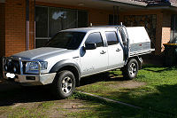

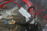

First pic is the new truck, second shows battery in position with dual Anderson plugs, third shows the power take off for the light and cigarette lighter in pic 4. I fixed the battery in place using some angle aluminium pop riveted to the base of the toolbox, topped with a sheet of ply to isolate the battery from the tool box itself. The tie down is a strap hinge with most of the loop around the pin of the strap cut away so it can be angled under and drop down to secure it, then fixed down with a standard battery tie down at the other end.
Posted in Uncategorized | No Comments »
July 20th, 2011
Not much has been happening, so not much to report in terms of costs.
Senturion provided us with steel to make the extra forwork – $227.50
Dry Creek Builders Yard for formply seconds – $120
Total project spend is now at $291,385.83
House only is now $77,433.33
Cost per square metre is now $268.87
Posted in Project Costs | No Comments »
June 19th, 2011
A run of wet weekends has spoiled our dirt parties over the past few weeks. On the 2 occasions we could have done some work we have been suffering through colds and sniffles our boy keeps bringing home from kinder gym or playgroup. Such is life.
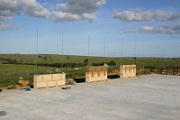
Still we did get up there this weekend and spent a full day organising all the bits and pieces so the next fine break we get we can spend building the actual house. Our neighbour has electrically fenced off our woodlot and the house area and has his cattle happily grazing in the paddock in pic1. We went for a bit of a wander as well to have a look at how our tree plantings have progressed since around this time last year. Some of these trees have grown more than a metre since we planted them and you can see Elise standing amongst them and indicating actual height in pic 2 & pic 3.


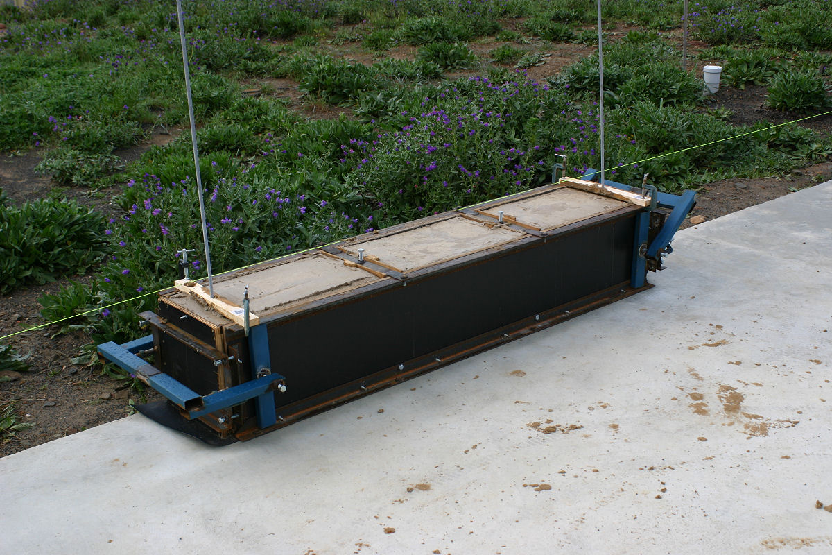
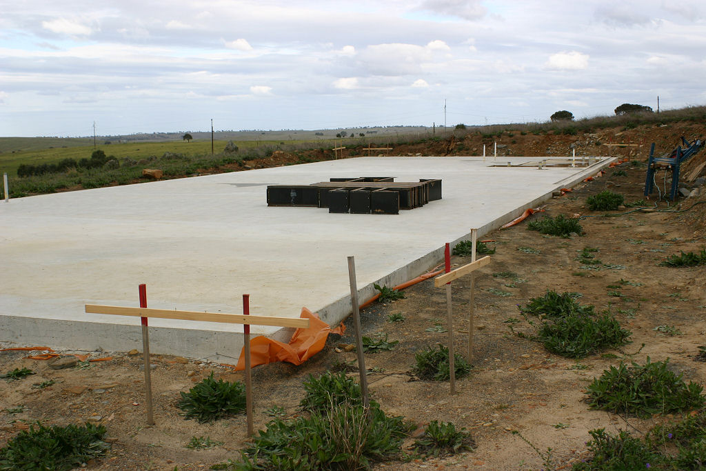
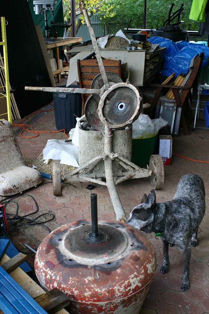
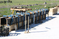
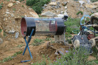
The trommel was assembled as in the first pic below and tested for workability and it performed flawlessly. The width of the cage is just smaller than our builders barrow so all that needs to be done is throw dirt in, empty barrow and occasionally empty the barrow of rocks on the other end. I reckon we’re seeing far less rock come out the other end compared to the shaker sift where half the lumps were just compacted dirt and not rock at all. You’ll notice I welded up a quick support stand to keep some of the pressure off of the axle end of the barrel. Second pic is all the formwork on the slab ready to go.

Posted in Building Progress | No Comments »
June 19th, 2011
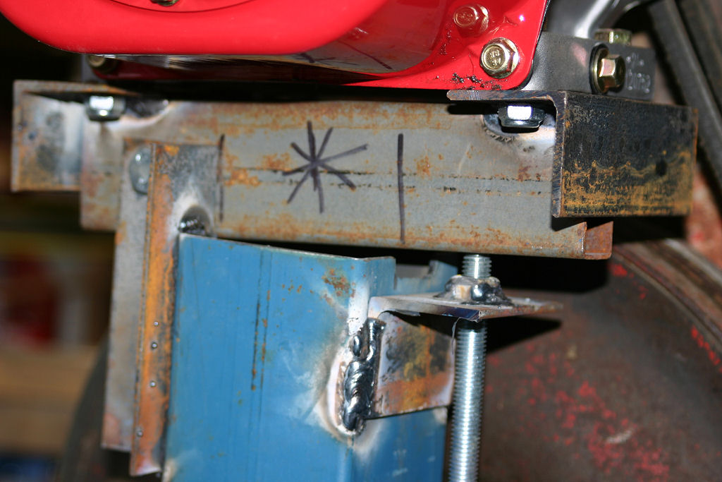
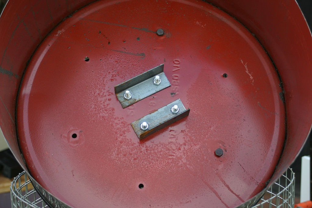
All bolted together the working end of my newest toy looks like thumb 1. By this time I had decided a secondary panel inside the drum to keep things working away was not necessary, and instead I split a length of 100x100x2mm steel to make two large pieces of angle. I used these to both joint the drum ends and the screen together as well as provide agitation in the drum as the material tumbles around. Thumb 2 shows where all the rock eventually tumbles out of the drum. Last pic shows how I attach most materials that are welded end on. Tacked into position first and then a piece of angle iron on at least 2 sides is fully welded to provide extra rigidity.


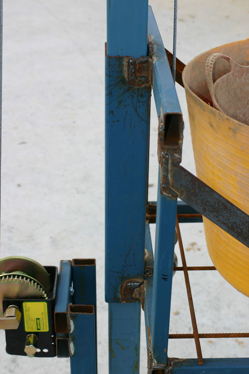
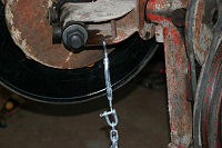
Since belts stretch and need constant tensioning I added in a simple system to achieve this as seen in the next thumb. To tension the belt all that needs to be done is the 100mm bolt is screwed further into the assembly, pushing the entire engine up. The opposite end is bolted through 2 pieces of angle to act as the pivot point. Last thumb shows how the angle of the drum can be adjusted should it need to be set up on sloping ground, a few cranks on the turnbuckle can raise or lower it quickly and easily.

Posted in Tips and Techniques, Uncategorized | No Comments »
June 12th, 2011
The earth sift I made works as it was intended. BUT…. it is time consuming and it does take a toll on the body having to bang the sieve screen to get dirt to fall through it. At this time of the year the clays in the soil are also activated and you end up with a “sloppy” rock wobbling around on top of the screen.
Trommels are an industrial machine that are basically a perforated rotating drum on a slight angle. The material to be sifted is dumped in the higher end, the drum rotates with anything smaller than the screen passing through it as it tumbles with the larger particles passing through the lower end and into a spoil pile (or as in mining into a crusher).
So here is the simple outline of how I made a trommel to make my job of sifting soil for the walls easier.
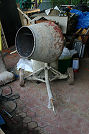
First job was to secure a cement mixer, a quick tour through eBay and their localised subsidiary Gumtree found a suitable cement mixer for sale for $180. I used this as a base since a trommel needs a slow and controlled spin and a cement mixer already has the gearing in place to achieve this. Important note is that mixer had a bowl that was bolted to the gearing. The first thumb below is the mixer I bought. Second thumbs shows bolts cracked and the bowl removed to expose the gearing.
I picked up an ex food 44 gallon drum for $15 and an elcheapo 5.5HP honda knock off engine for $177 from Paramount Browns. The drum I sat in a square frame on casters and used the momentum of the grinder to cut a 100mm lip into the lid and then separate the drum into hoops, roughly a third of the drum per section as in the third thumb.
Also in the third thumb is the most difficult part by far – getting the 25mm galvanised wire sheet ($42 from Senturion Steel) to roll. That took several ratchet straps and a lot of swearing to roll it back on itself. I’ll leave that strapped up until the frame of the drum is complete and then I will unleash it and trim the excess.
Last thumb in this group shows the new axle for the trommel, it’s a very large 1&1/8 x 10 inch high tensile bolt which also happened to be very expensive at $38.


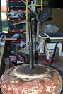
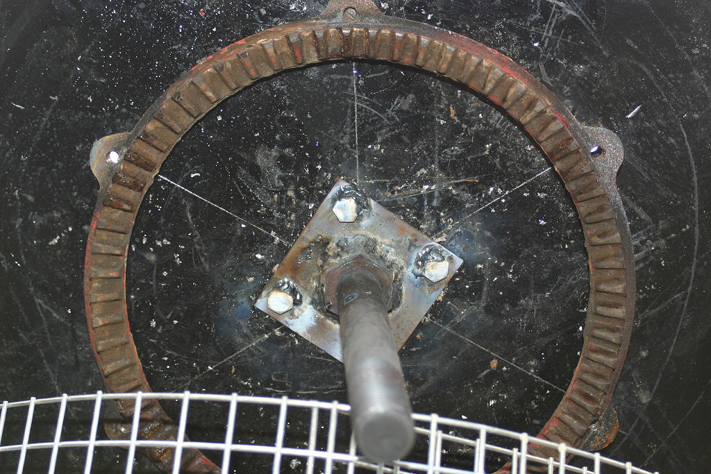
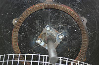
First thumb in this group shows how the gearing works in the mixer. Second thumb shows the axle and gearing in place. The bolt was welded to a 5mm plate with a hole drilled into each corner of it. The most thinking of the job involved working out how to centre the axle in the base of the drum.
I did this by subtracting the diameter of the gear ring from the diameter of the drum, halved the result then used a ruler to mark that measurement in as many places as possible around the rim of the drum. From there I positioned the gearing ring and marked the bolt holes. Once the holes were drilled I scratched a line between opposing sides and that gave me the centre of the drum. Since there are six holes and the bolt head is hexagonal, simply lining up the “corners” of the bolt head with the scratched lines centred the axle assembly perfectly. Holes were drilled, bolts welded to the plate and internally the bolts were secured using a small piece of angle to spread some of the load as shown in thumb 3.


All up this gadget will come in under $500 and since the mixer bowl will be able to be restored I’ll be able to sell it once the project is finished as either a mixer, a trommel or both.
Posted in Tips and Techniques, Uncategorized | No Comments »